April 2013
CURRENT AND POTENTIAL ROBOTIC AWJS
Mohamed Hashish
Flow International Corporation
www.flowcorp.com
ABSTRACT
5-axis gantry robots and 6-axis articulated arm robots have been used with plain waterjets for many applications especially in the automotive industry. This paper is on extending the use of these robots to abrasive waterjets and for a much wider range of applications. The integration of the abrasive waterjet process on robotic arms has been successfully developed to address the end effector, supply of high pressure water and abrasives to the cutting head, and operational safety. Off line programming, calibration, and inspection are discussed. Advanced software packages typically used in the aerospace industry have been successfully adapted. The need for enhanced accuracy performance using first article inspection results is discussed. A few case studies are presented in this paper addressing composite trimming for wing skins used in aircraft and wind turbines and for stone cutting with hybrid processes. It was found that 6-axis robot arms can easily be implemented when moderate accuracies, from 0.010 inch (0.25 mm) to 0.015 inch (0.38 mm) are specified. However, accurate calibration and first article inspection procedures were found necessary to obtain accuracies below 0.01 inch (0.25 mm). Much tighter accuracies are achieved with stiff gantry systems.
1. INTRODUCTION
Today, thousands of multi axis robotic cells are deployed worldwide in a variety of high production environments. These include; manufacturing of standard and customized components, prototype designs, and low & high volume mass production of large and medium batch sizes for OEM and aftermarket sectors. In these applications, the robot accuracy and repeatability have been sufficient.
For accurate processing of the workpiece and especially cutting with a beam-like cutting tool such as waterjet and abrasive waterjet (AWJ), more understanding of all aspects and process variables that affect accuracy is necessary. These variables can stack up and result in out-of-tolerance parts. These variables could be related to the manipulator, fixture, material, tool/process, and the environment. The robot, for example is a complex assembly of interconnected links, gears, gear trains, servo drives, harmonic drives and even belt drives. These result in positional and path errors which need to be compensated for. Also, recognizing the idiosyncrasies of the material, such as homogeneity, shrinkage, warping, etc. will lead to minimized errors by proper compensation (1-3)
In this paper, we first address manipulators for waterjet applications covering gantry and 6-axis robots. Then, we will address AWJ applications such as trimming, cutting, and shaping using 6-axis robots with focus on composite trimming. Conclusions are listed at the end of the paper.
2. MANIPULATORS
In this section we address 5-axis gantry robots and 6-axis robotic arms because they are the most used in multi-axis waterjet cutting.
2.1 5-Axis Gantries
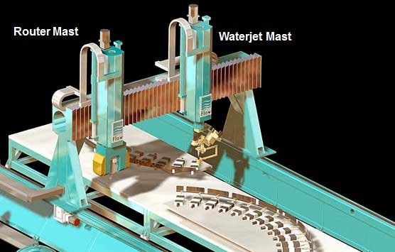
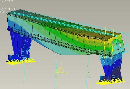
The 5 axis gantry systems represented by Figure 1, are Cartesian manipulators and are designed with relatively high degree of structural stiffness in order to achieve the required accuracy. It is typical in the design of these systems to study their structural, kinematic, and dynamic behaviors using analysis software packages such as finite elements. For example, Figure 1 (right) shows the results of a finite element analysis used to determine the deflection of a gantry bridge under given loads. The analysis may also include thermal deformation and whether environmental control will be required or not based on the required part accuracy. The deflection data can be used for compensation in order to obtain more accurate results.
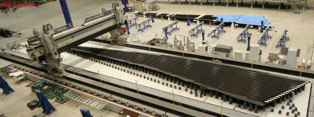
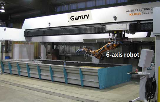
These gantry units are sometimes installed on a machine tool foundation and housed in a controlled environment to maximize stiffness and minimize the thermal effects. When mechanical end effectors such as routers are integrated into waterjet gantry systems, the stiffness requirement becomes the driving factor for machine construction. Helical rack and precision gear boxes and closed loop control systems contribute to smooth motion and high accuracy. Before using these machines, the linear axes are compensated using laser interferometers. Linear encoder scales are also used to increase the accuracy on large scale systems. Figure 2 shows a picture of a typical 50-m long hybrid waterjet-router gantry system used for trimming wing skins for the Boeing 787 (4).
2.2 6-Axis Robotic Arms
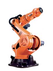
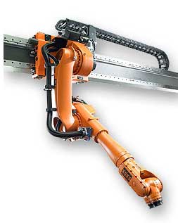
6-axis articulated arm robots have been used in a very wide range of industries such as automotive, electronics, and entertainment due to their flexibility, relatively low cost, and reduced footprint. These robotic arms can also be mounted in a variety of ways based on the application such as floor mount, ceiling mount, gantry mount, wall mount, etc. as shown in Figure 3.
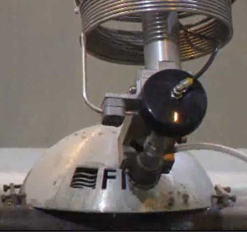
Although highly repeatable, robots are not accurate until they are “mastered”, i.e., compensated. They are typically manually taught by eye from a teach pendant, Figure 4, using a ‘point-to-point’ format. The programmer may choose to use a custom pointer as the simulated Tool Center Point (TCP) or a peripheral laser pointing device, aimed at the target zone or they may simply guess and cut a part, measure the deviations and correct it with another pass and so on. During this procedure the operator will program the path, consisting of lines and circles and also define speeds, corner positioning etc. and assign any I-O (inputs and outputs) to control or monitor external functions. These external devices can be the nozzle, vacuum system, clamps etc. The robot can also be oriented in a variety of positions to suit the work environment. Moving forward from this manual procedure to an offline programming environment will enable elimination of the teach pendant. This will require a custom post processor and process specific offline programming software relative to the particular brand of robot. In order to do this, the robot, the end effector TCP and the work holding fixture must be defined in the real world. As with the gantry systems, robot rigidity is also a very important factor to ensure high accuracy calibration.

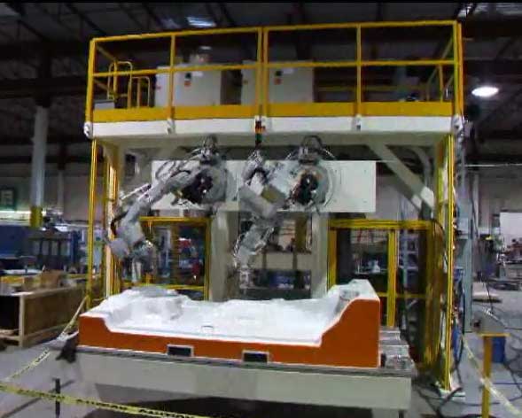
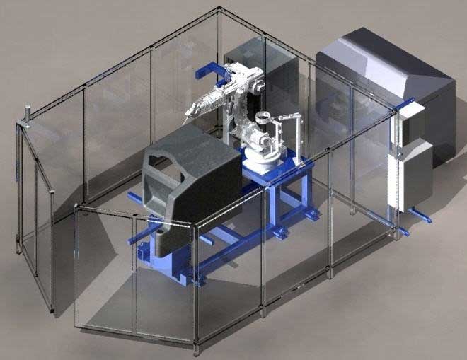
Robots are integrated in several system styles such as open and enclosed systems, Figure 5. Also, more than one robot can be used on the same part. In this case, off line programming will be critical.
2.3 AWJ Robotic Cutting
Waterjet robotic cutting has been early introduced due to the advantages of both robots and waterjet. For example waterjets (without abrasives) have been used for cutting and trimming a wide range of automotive interior materials (5-7). Among these are:
• Floor carpets and roof liners.
• Dash sound insulation material.
• Plastic/Fabric composites (i.e. rear shelf and transmission tunnel components)
• Sheet molded composites (SMC)
• Glass fiber components (body panels etc.)
• Carbon fiber and /or Aramid fiber composite
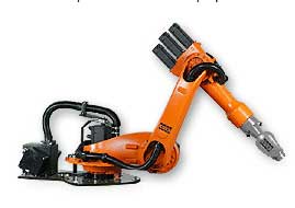
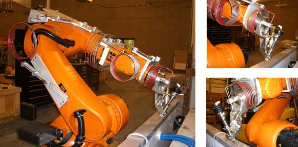
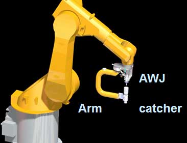
Recently, abrasive waterjets (AWJ) were integrated with robots to capitalize on their flexibility. However, this introduced new significant challenges related to abrasive feed, accuracy, speed range, and safety. Figure 6 shows an example of an AWJ-equipped robot arm.
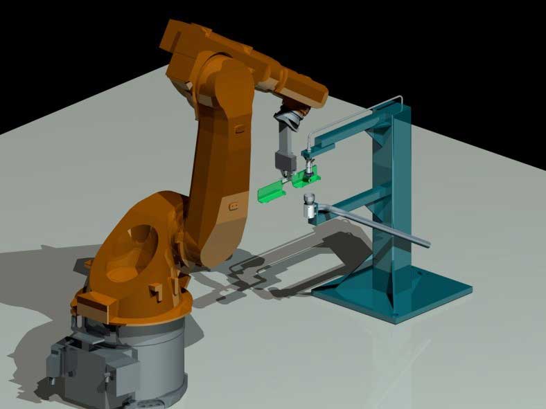
As discussed above, robots can be mounted in different ways based on the application. For AWJ use, floor mount AWJ systems have been commercialized. Also, Figure 7 shows alternative methods to using robotic AWJ arms either on a stationary frame or on a single axis gantry.
3. SELECTED AWJ ROBOTIC APPLICATIONS
3.1 3D AWJ Cutting and Shaping
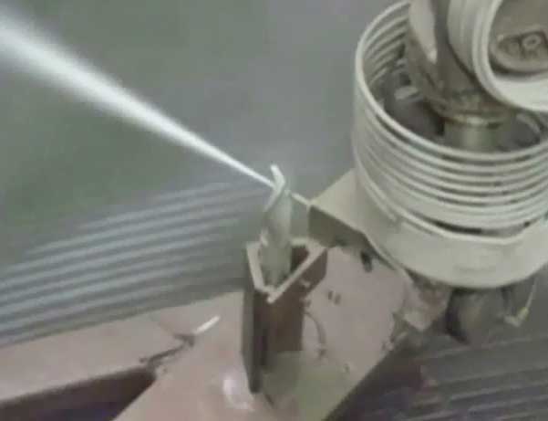
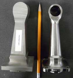
It has been shown that AWJ has great potential for 3D cutting and shaping (8, 9). Due to the 6 degrees of the freedom offered by robotic arms, 3D machining and shaping with AWJ may be-come highly feasible. For example, a complex geometry as shown in Figure 8 (left, center) can be machine without re-orienting the workpiece. A block of material can be cut to produce a near net shape part as shown in Figure 8 (right). The addition of a rotary axis will allow machining additional features such as surface of revolution. This can be of a significant time saving in actual production environment. For example, machining the nozzle injector shown in Figure 8 (right) can be started by cutting segments out of the original raw bar or rod and then some sections can be turned to minimize the subsequent milling and finishing processes. Analysis showed that over 50% time saving can be obtained for the injector nozzle part but equally important, not all the material need to be converted to chips and thus a higher residual value is obtained with this approach. Cutting on 3-D parts can also be accomplished as shown in Figure 9.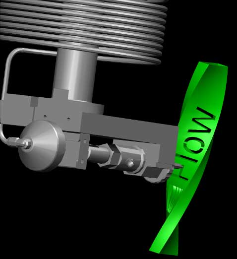
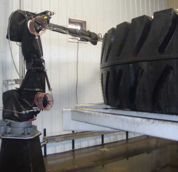
3.2 Tire Cutting
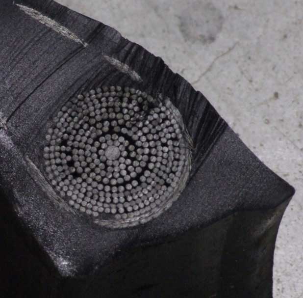
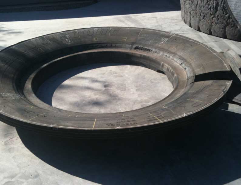
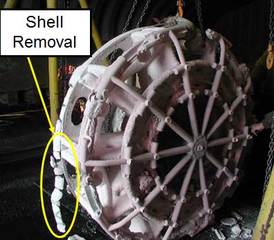
In the mining industry, giant tires are used on several mining equipment. These tires may be over 2-m in diameter and weigh over a metric ton. They are subject to the manufacturer’s scrutiny to avoid costly premature failure. An AWJ tool has the significant advantage of being non-thermal and non-mechanical making it a most suitable tool for cutting tire to enable true structural analy-sis to for Quality Assurance testing of the rubber and steel wire composition in the tread, side-walls or bead. Typically “dog-bone” sectioning of the tire is made at several locations for testing and evaluation. Also, when tires fail, the failed areas are cut out. A 6-axis robot equipped with an AWJ is manually programmed by the operator to dissect and remove any failed relatively small section or complete cross section of the tire. Figure 10 shows a robotic AWJ used to cut up coupons from a large tire. Observe the steel wires that need to be cut. The full side wall was cut by mounting the tire on a turntable and rotating it.
3.3 Stone Cutting
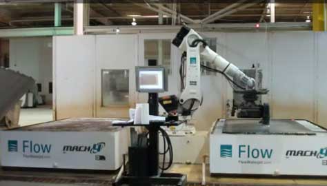
Combining state-of-the-art technologies to production grade work cells is the next evolutionary step for multi-axis robots. Utilizing a vision system and photographic imaging for identifying part location and alignment to tool path math data with user friendly software allows simple operator interface control of machine tool to cut complex shapes in materials such as stone with AWJ technology and straight linear cuts using mechanical diamond circular saw technology for optimal speed. Figure 11 shows a robotic end effector with both AWJ cutting head and a saw. A common cell is to use two work stations (cutting tables) as shown in Figure 11. This dual table de-sign maintains an efficient use of plant floor space by locating the robot centrally between the two cutting tables allowing one side to be cutting whilst the opposite side is clear and open for operator loading and unloading thus maintaining continuous productivity.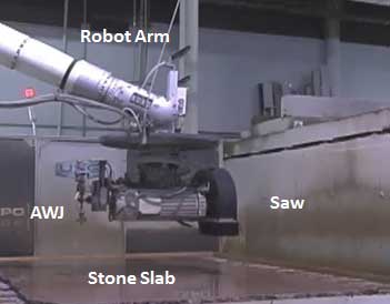
3.4 Degating and Deflashing
Complex castings may require gates and risers in unusual places to achieve the desired shape or product, see Figure 12. In some cases the cut line is not linear and is problematic for conventional mechanical band saws, circular saws or dedicated tooling of shear brakes to handle. In these cases, operator safety is also a consideration due to broken blades or bodily injuries. The AWJ tool offers great advantages for this application because of its omnidirectional cutting capability and without any heat affected zones. However, precaution must be used regarding the direction of the emerging jet on the “back side” of the cut. The programming is done manually by teaching the path of the cut. In some sophisticated systems, machine vision can be used instead. In the cases where the exiting jet may affect the casting, protection plates may be used or the area is avoided and then cut mechanically. Special cutting heads has been used to reach in tight spaces or to cut adjacent to a wall. Mounting the casting on a turntable and subjecting it to the AWJ will results in cleaning and removal some flash material. The abrasives may be turned off in some cases to avoid cutting or eroding the workpiece.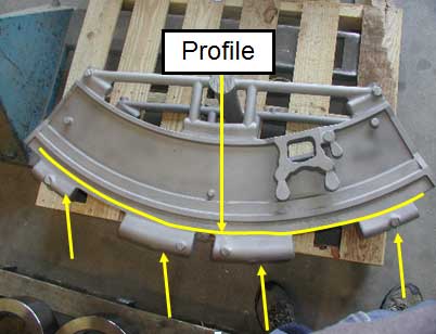
3.5 Composite Trimming
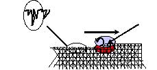
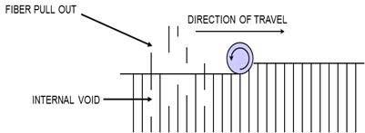
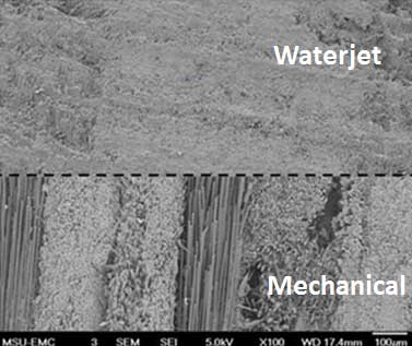
Most trimming requirements are within the accuracy of robotic arms. This makes them of high potential for composite trimming using waterjets which is needed in many applications. For example carbon fiber composites are used in aircraft structures and they are difficult to machine with conventional tools (10, 11). These tools often result in localized heat affected zone which melts the resin inducing a recast state and evidential micro cracks as illustrated in Figure 13. Also, they may cause internal voids due to fiber pull out, Figure 13 (right). In addition, controlling the composite cut surface finish is difficult because of the anisotropy of the material unlike AWJ cutting which is much less sensitive to this effect. AWJ offers great advantages over conven-tional tools regarding speed, lifetime, and quality. For example a 0.400 inch (10mm) router bit will last on average 40 minutes to 1 hour, whereas the average AWJ nozzle with a 0.040 inch (1 mm) stream diameter will last over 80 hours continuous cutting. A great advantage of AWJs is that it is non-thermal, (no heat or mechanical stresses), no fiber pull-out, no delamination and the cutting speed is typically twice as fast. The fixturing required can be designed very light weight as the process induces less than 4.4 lb. (2 kg) of thrust force while cutting. Figure 14 shows a micrograph comparing AWJ to mechanical cutting.
3.6 Aircraft Applications
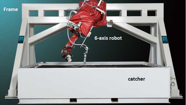
AWJ have been used extensively in many aircraft composite cutting and trimming applications since the late 1980s. Example aircraft and corresponding AWJ-machined components are given in reference (4).Five axis gantry systems with dual masts for waterjet and mechanical routing have been the standard systems for the above applications. Six axis robots promise to compliment the standard gantry systems for some trimming applications. Figure 15 shows a model of a robotic AWJ trimming unit. Observe that the catcher cup arm needs to swing (6th axis) as not to collide with the structure being trimmed. Instead of manipulating the jet, the workpiece may be manipulated with a robotic arm under a fixed jet. This approach may be useful for some applications.
In addition to shape trimming, robots may also be useful for end trimming and shape cutting. For example, 5-axis AWJ was used to drill access holes at the roots of stringers which can also be done with 6-axis arms using an appropriate end effector. To trim the ends of stringers which may be in the shape of an I-beam, as shown in Figure 16, or T-beam, 6-axis manipulation will greatly simplify this process.
3.7 Jet Engine Hole Drilling Application
The use of robotic arms in jet engine applications has been limited to stripping applications using plain waterjets. Typically, cutting and drilling in jet engine parts requires more accuracy than robots may be capable of providing and thus many roughing applications could benefit for AWJ robotic cutting. For more accurate cutting of a given part, compensation could be used.
A significant advantage of using robotic arms is the ability to use more than one jet on the same part. For example, a number of robots could be used to drill small diameter holes on a nacelle part. It was shown that 30,000 holes were drilled at about 0.9 sec hole-to-hole time, so one jet will drill a part with 100,000 holes in about 30 hrs. and thus four robots will drill this part in one shift. Figure 17 (left) shows a composite nacelle mock-up drilled with AWJ while Figure 17 (center) a close up of drilled holes in a flat composite part.
Figure 17 (right) shows another example of drilling through silicon carbide/Silicon carbide composite flame holder part inside a jet engine. These holes are drilled at several angles to achieve maximum cooling effect. With a 6-axis robot, and after tool center pint (TCP) compensation, parts can be drilling to better than 0.25 mm location accuracy which is closer to robot repeatability specification.
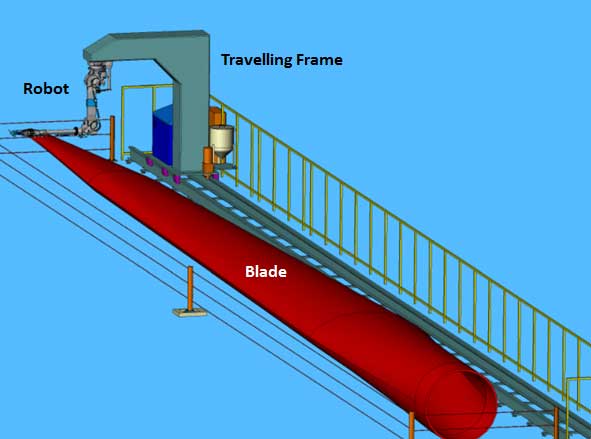
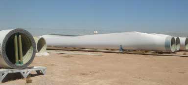
3.8 Wind Turbine Blade Trimming
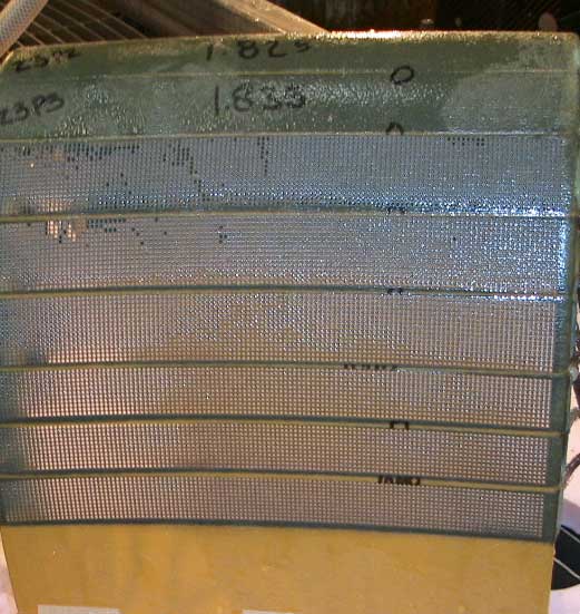
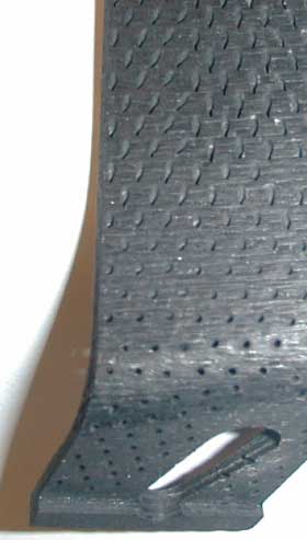
Wind turbine blades are made of fiberglass and they have a round root and an aero foil shape blade. To trim the seam between the halves of this blade, the current approach is manual using mechanical tools. An alternative approach is to use 6-axis robots. Figure 18 shows a robot mounted frame rail for the trimming of relatively long wind turbine blades. The seam between the upper and lower shell is trimmed using a special nozzle that cuts very close to the root of the joint.
4. CONCLUSION
5-axis robots have been in use with AWJ cutting of composites since the late 1980s for a wide range of aircraft components achieving accuracies of +/- 0.002 inch (0.05 mm). The use of spe-cific, rigid 6-axis robots is now emerging as their accuracies are now proving to be better than +/- 0.010 inch (0.25 mm). The calibration process allows the robot and the workcell to become more “accurate”, by precisely defining the actual or “true” kinematic model of the robot-cell, and off-setting and compensating for the differences to the CAD or “ideal” kinematic model. The use of robotic cutting and drilling cells is emerging for such parts as composite nacelles and small scale parts such as clips, fairings, covers etc. as a very cost effective solution.
REFERENCES
1. Hashish, M., and D. Snider (2010) “Robotic Waterjet Cutting,” Proceedings of the 19th Inter-national Conference on Water Jetting, BHR Group publ., 2010, pp.397-407
2. Snider, D., and Hashish, M., (2010) “Precision waterjet cutting in the waterjet cutting in the composite industry utilizing multi-axis robots for high quality machining,” COMPOSITES 2010, American Composites Manufacturers Association February 9-11, 2010, Las Vegas, Nevada USA.
3. U.S. Pat. 5,731,256 (Mar. 24, 1998) John Owens, RSL, Newcastle upon Tyne, Great Britain; “Off-line Programming Software for Control of Industrial Robots”
4. Hashish., M., “AWJ Trimming and Drilling of Composite for Aircraft Structures, “ Proceed-ings of the 9th Pacific Rim International Conference on Water Jetting Technology, November 20-23, 2009, Koriyama, Japan
5. Hashish, M., (2003) “Waterjet Applications in the Automotive Industry,” Proceedings of the 7th Pacific Rim international Conference on waterjetting Technology, Jeju, Korea, October 27-29, 2003
6. Snider, D., 1989 “Automated TPO Trimming for Quality and Production,” Proceedings of the 5th American Waterjet Symposium WJTA, Toronto, CA.
7. Cook, R., and Wightman, D., (1988) “Automotive Applications of Waterjet Cutting,” SME paper number MR88-140, WESTEC, March.
8. Hashish, M., (1998) “The waterjet as a Tool,” Proceedings of the 14th International Water Jet Cutting Technology Conference, BHR group, Brugge, Belgium, October
9. Annoni, M., Monno, M., Vergaria, A. (2003). Abrasive Water Jet in Rapid Prototyping. Journal of Manufacturing Systems. Vol. 32, No 1, pp. 63-74.
10. Ramulu, M., and Taya, M., (1988), "An Investigation of the Machinability of High Tempera-ture Composites," Proceedings, 12th Conference on Composite Materials and Structures.
11. Kumanduri, R., (1997),”Machining of fiber reinforced composites,” machining Science and Technology, 1(1), pp. 113-152
12. Courtesy of Missouri State University, Electron Microscope Center, Dr. G. Munn, November 2009.
This article is excerpted from the April 2013 Jet News, a benefit of membership in WJTA-IMCA. For more information on membership, click here.